siga cr wiring diagram
6 Flat washers 6-32 Self-tapping screws UIO Motherboard. Diagram wiring wf wire neutral terminal ground bar ac.
Input Output Edwards Fire Safety
Epiphone sheraton ii pro wiring diagram.

. Wiring alarm cr input ct2. Siga cr diagram wiring cc1 module alarm fire est modul. All wiring is power-limited and supervised.
Each terminal on the module is limited to a single conductor. Before replacing a SIGA-CC1 module tag the wires to ensure correct reconnection. Make the wiring connections as shown in Figure 1.
16 Pictures about Siga-cr Wiring Diagram. Anet a8 sensor leveling nc diagram wiring npn proximity prusa 3d i3 using instructables mosfet. The fire alarm control panel provides this function.
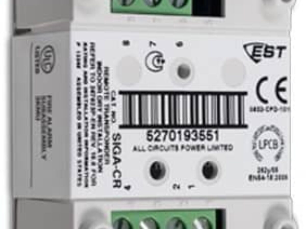
Test resistors are supplied with the SIGA-CT2 to prevent trouble signals on unused circuits during installation. 31 scion tc stereo wiring diagram. The Edwards SIGA-CRH High Power Control Relay is an addressable device design for interface applications that require a high voltage high current relay.
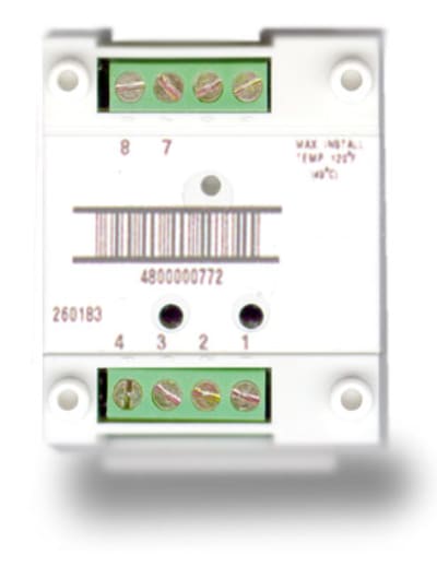
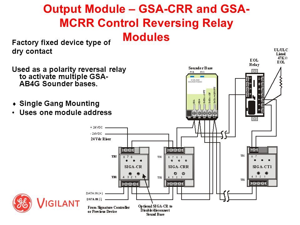
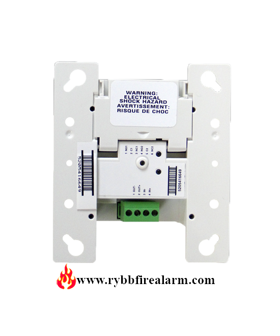
When connecting field wires. SIGA-CR Control Relay Module Installation Sheet Description The SIGA-CR Control Relay Module is an addressable device that provides one Form C dry contact output relay. The SIGA-CRR is used to activate Refer to the Signature loop controller installation sheet for SLC wiring specifications.
Kia Soul Ev Wiring Diagram - firstkiarumorco Yamaha Chappy lb80 wiring diagram Yamaha QT50 luvin and other nopeds. Use separate knockouts for the SLC wiring and the high voltage wiring. A test resistor is supplied with the SIGA-CT1 to prevent trouble signals on unused circuits during installation.
All wiring is power-limited and supervised. Issue 72 SIGA-CR Control Relay Typical Wiring Modules will accept 18 AWG 075mm2 16 10mm 2 14. Edwards EST SIGA-CR Control Relay Module Life Safety Consultants CTP-LBI-AP-U-HA-AZ-SA-127798 Transponder-coded.
Two identical sets of. Siga Cr Wiring Diagram Siga-cr Wiring Diagram and also MR_3640 For Allison 3000 Wiring Schematic Wiring Diagram. UIO motherboard terminals are suited for 12 to 18 AWG 25 mm2 to 075 mm2 wire size.
Siga cr cc1 diagram wiring edwards module alarm fire est. Page 3 of 6 D ATA S H E E T 85001-0239 Not to be used for installation purposes. The SIGA-CC1 module does not supervise the riser.
17 Pics about Siga-cr Wiring Diagram. 14 Pics about Siga-cr Wiring Diagram. Make sure that power-limited and nonpower-limited wires will have.

Uberspannungsschutz Pv Photovoltaik Spd 1000vdc 3 Polig Typ 2 C Tuv Ebay
![]()
Transfer Switch Manual
Signature V Series Detectors And Modules Ppt Video Online Download

Signal Modules Siga Cc1 Mcc1 Cc2 Mcc2
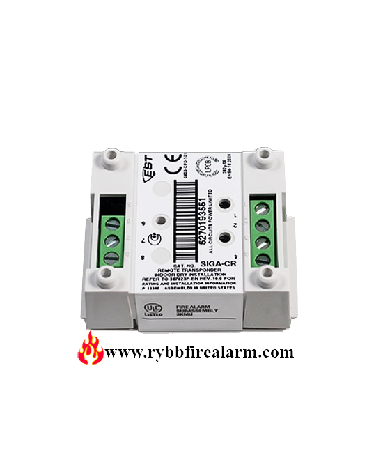
Edwards Siga Cr Control Relay Rybb Fire Alarm Parts Service Repairs

Input Modules Siga Ct1

Est Siga Cr Pdf Pdf
Signature V Series Detectors And Modules Ppt Video Online Download

Est3 Siga Ct1 Ct2 Cc1 Module Connection Fire Alarm System Full Details Youtube

Fire Alarm Ct1 Ct2 Cr Cc1 Um Module Connection And Wiring Diagram Firealarm Firealarmsystem Youtube

Edwrads Monitor Module Siga Ct1 Siemens Monitor Module Wholesaler From New Delhi
Edwards Siga Crh High Power Control Relay Rybb Fire Alarm Parts Service Repairs
Edwards Est Siga Cr Control Relay Module
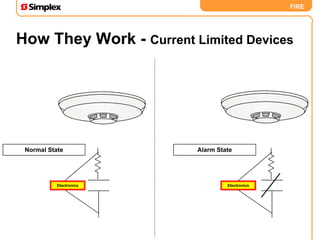
Back To Basics

Fire Alarm System Edward Est Brighter Impact

Xvd2 02v Smooth Vent Valve Supply Line Xvd2 02s Xvd2 02v Smc Misumi South East Asia
Est 3 Siga Ct 2 Pdf Electrical Wiring Amplifier